Benefits of Litz Wire
How litz wire can transform your product
When manufacturing motors, transformers, and other electromagnetic devices, magnetic fields are created by current in a wire. By raising the frequency, you create stronger fields and higher coupling, resulting in a loss in the materials due to two effects – Skin Effect and Proximity Effect.
As the frequency rises, the current migrates to the skin and is pushed away by the field of its neighboring strand, making the core of the conductor useless. Litz wire mitigates both the Skin Effect and Proximity Effect losses. New England Wire Technologies designs with individual strands that are smaller than the skin depth and transposes those strands throughout the length of the wire. The correct size of the wire is based on the frequency of the application.

Reduce AC losses in high frequency windings
Increased efficiency
Mitigation of Skin Effect
Mitigation of Proximity Effect
Minimize eddy current losses
Lower operating temperatures
Reduced footprint of final product
Substantial weight reduction
Avoidance of “hot spots”
What is Litz Wire?
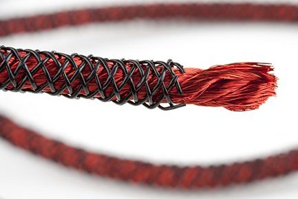
The term “Litz,” is derived from the German word “Litzendraht” which describes a conductor consisting of separately insulated strands twisted or braided into a uniform pattern. This design equalizes the flux linkages and reactances of the individual strands causing the current to spread uniformly throughout the conductor. The resistance ratio (A.C. to D.C.) then tends to approach unity, which is desirable in all high-Q circuit applications.
New England Wire Technologies offers unlimited Litz wire constructions in all 9 type variations with multiple choices of insulation to meet agency and/or specific customer voltage withstand requirements. Because of the low electrical losses and ease of solderability, the enamels commonly used for insulating individual strands are Polyurethane and Polyurethane with a Nylon topcoat. However, other insulations may also be used. In many cases, Litz wire is insulated with an overall single or double wrap, or serving, of a textile, but is also available unserved. Tape and extruded plastic insulation options are also available.
Litz Design
Typically, the design engineer requiring the use of Litz knows the operating frequency and RMS current required for the application. Since the primary benefit of a Litz conductor is the reduction of A.C. losses, the first consideration in any Litz design is the operating frequency. The operating frequency not only influences the actual Litz construction but is also used to determine the individual wire gauge. The table below highlights the recommended wire gauge versus frequency for most Litz wire constructions.
Recommended Wire Gauge vs. Frequency
| Frequency | Recommended Wire Gauge | Nominal Copper Diameter Over Copper (in) | DC Resistance OHMS/MFT (Max) | Single Strand RAC/RDC "H" |
|---|---|---|---|---|
| 60 Hz to 1 KHz | 28 AWG | 0.0126 | 66.37 | 1.0000 |
| 1 KHz to 10 KHz | 30 AWG | 0.0100 | 105.82 | 1.0000 |
| 10 KHz to 20 KHz | 33 AWG | 0.0071 | 211.70 | 1.0000 |
| 20 KHz to 50 KHz | 36 AWG | 0.0050 | 431.90 | 1.0000 |
| 50 KHz to 100 KHz | 38 AWG | 0.0040 | 681.90 | 1.0000 |
| 100 KHz to 200 KHz | 40 AWG | 0.0031 | 1152.30 | 1.0000 |
| 200 KHz to 350 KHz | 42 AWG | 0.0025 | 1801.00 | 1.0000 |
| 350 KHz to 850 KHz | 44 AWG | 0.0020 | 2873.00 | 1.0003 |
| 850 KHz to 1.4 MHz | 46 AWG | 0.0016 | 4544.00 | 1.0003 |
| 1.4 MHz to 2.8 MHz | 48 AWG | 0.0012 | 7285.00 | 1.0003 |
Traditional Litz Wire Applications
- Stator Windings
- High Frequency Inductors
- Power Transformers
- Motor Generators
- Hybrid Transportation
- Wind Turbine Generators
- Communication Equipment
- Marine Acoustic Control Systems
- Induction Heating Applications
- Sonar Equipment
- Radio Transmitter Equipment
- Switch Mode Power Supplies
- Ultrasonic Equipment
- Linear Motors
- Sensors
- Antennas
- Grounding Applications
- Wireless Power Systems
- Electric Vehicle Chargers
- High Frequency Chokes
- Coils
- High Frequency Motors
- Medical Device Chargers


