Modern Maglev Technology and High-Efficiency Electromagnetic Design

Magnetic levitation (maglev) technology—once a scientific curiosity rooted in naturally magnetized lodestones—has evolved into a mature engineering platform supporting high-speed transportation, precision rotating machinery, grid stabilization, and advanced aerospace concepts. What began as simple observations of magnetite aligning to Earth’s magnetic field has become a sophisticated field of controlled electromagnetic force, power electronics, and advanced conductor design.
Today, maglev systems are enabled by high-power electromagnetics, real-time control systems, superconducting materials, and low-loss conductors such as Litz wire—each contributing to improved efficiency, reliability, and scalability.
High-Speed Maglev Transportation
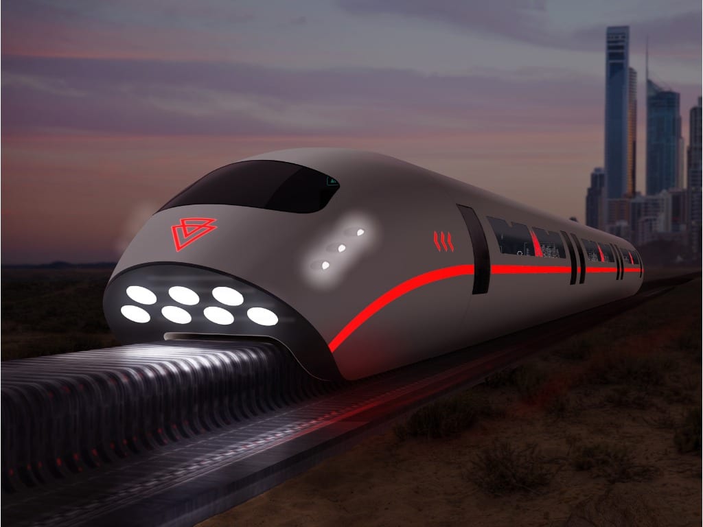
Commercial maglev rail is no longer theoretical. Operational systems in China, Japan, and South Korea routinely transport passengers at speeds exceeding 430 km/h (267 mph). Japan’s superconducting EDS (Electrodynamic Suspension) SCMaglev system has demonstrated speeds above 600 km/h (373 mph) during testing.
Despite technical success, infrastructure cost remains the principal barrier to widespread adoption. Dedicated guideways, precision alignment requirements, and high-capital construction continue to limit deployment compared to high-speed rail operating on upgraded conventional track.
Two Primary Maglev Architectures
1. Electromagnetic Suspension (EMS)
EMS systems use controlled electromagnets mounted beneath the vehicle to attract it upward toward a ferromagnetic rail. Active feedback systems maintain levitation gaps typically in the millimeter range. Propulsion is provided by linear motors integrated along the guideway.
Advantages:
- Continuous levitation at zero speed
- Mature industrial control systems
- Reduced cryogenic requirements
Challenges:
- Tight positional control tolerances
- Continuous power requirement for lift
2. Electrodynamic Suspension (EDS)
EDS systems rely on superconducting onboard magnets interacting with conductive or coil-based guideways. Motion induces opposing currents in the track, producing repulsive lift forces through Lenz’s Law. Levitation gaps are larger—often several centimeters—improving mechanical tolerance.
Advantages:
- Larger air gap
- Passive lift generation once at speed
- High-speed stability
Challenges:
- Requires roll-on wheels for low-speed acceleration
- Cryogenic cooling systems for superconducting magnets
Magnetic Bearings: Contactless Rotation at Scale
Magnetic bearings eliminate mechanical contact between rotating and stationary components, reducing friction, wear, lubrication requirements, and maintenance.
Passive Magnetic Bearings (PMB)
PMBs rely primarily on permanent magnets. However, as defined by Earnshaw’s Theorem, purely static permanent magnet configurations cannot achieve stable levitation in all degrees of freedom. Therefore, passive systems require mechanical constraint or hybrid stabilization.
Applications include:
- Satellite flywheels
- Energy storage systems
- Vacuum-environment rotating equipment
Active Magnetic Bearings (AMB)
AMBs combine permanent magnets, electromagnets, sensors, and digital control systems to dynamically stabilize a rotor. Modern AMB systems incorporate high-speed digital signal processing and fault-tolerant architectures.
Applications now include:
- High-speed compressors
- Gas and steam turbines
- Grid-scale flywheels
- Hydrogen turbomachinery
- Medical ventricular assist devices
By eliminating mechanical friction, AMBs enable rotational speeds exceeding 60,000 RPM while maintaining long service life.
Grid-Connected Flywheel Energy Storage
As renewable penetration continues to rise globally, short-duration grid stabilization has become essential. In the United States, wind and solar now contribute more than 20% of total electricity generation in many regions during peak production periods.
Flywheel energy storage systems provide:
- Frequency regulation
- Voltage stabilization
- Short-duration backup power
- Renewable intermittency smoothing
Unlike chemical batteries, flywheels store kinetic energy in high-speed rotating masses supported by magnetic bearings. Round-trip efficiencies often exceed 85–90%, with cycle lives measured in hundreds of thousands of charge-discharge events.
Magnetic bearings are critical to minimizing parasitic losses and enabling long-duration standby with minimal maintenance.
Wind Turbine Evolution and Magnetic Concepts
Modern offshore wind turbines now exceed 15 MW capacity per unit, with rotor diameters over 240 meters. While most utility-scale turbines use conventional bearings and gearboxes or direct-drive generators, research continues into magnetic bearing-supported drivetrains to reduce maintenance in offshore environments.
Vertical-axis magnetic-assisted wind concepts remain largely experimental. While claims of gigawatt single-turbine capacity are not supported by current commercial deployments, magnetic load-reduction strategies continue to be studied for reducing mechanical stress and extending turbine life.
Aerospace Launch Concepts and Electromagnetic Acceleration
Electromagnetic launch systems for spacecraft remain in conceptual and prototype phases. NASA and private research groups have evaluated maglev-assisted launch tracks to reduce first-stage propellant requirements.
Concept studies include:
- Kilometer-scale electromagnetic acceleration tracks
- Vacuum tube acceleration systems
- Hybrid rocket-maglev launch assist
Although none have reached operational status, the underlying physics—controlled electromagnetic acceleration with linear motors—remains technically feasible. The primary barriers are structural engineering scale, cost, thermal management, and regulatory considerations.
As launch costs decrease due to reusable rockets, electromagnetic assist concepts continue to be evaluated as potential complementary technologies rather than full rocket replacements.
The Role of Litz Wire in Maglev and High-Frequency Electromagnetics
Across transportation, energy storage, and aerospace applications, maglev systems depend on high-efficiency electromagnetic coils operating at elevated frequencies and currents. Under these conditions, conventional solid conductors suffer from:
- Skin effect losses
- Proximity effect losses
- Eddy current heating
- Reduced power density
Litz wire—constructed from individually insulated strands woven in specific transposition patterns—dramatically reduces AC resistance. By equalizing current distribution across strands, Litz designs minimize thermal rise and improve efficiency in high-frequency systems.
Applications include:
- Linear motors
- Inductrack guideways
- Active magnetic bearings
- High-speed generators
- Power electronics inductors
In passive Inductrack-style systems, unpowered Litz-based ladder tracks allow moving magnetic arrays to induce lift currents without external energy input, improving simplicity and efficiency.
Engineering Toward Efficient Electromagnetic Systems
As industries electrify and power density demands increase, conductor design becomes a system-level decision. Optimized Litz constructions enable:
- Higher operating frequencies
- Reduced thermal hotspots
- Compact winding geometries
- Improved system reliability
For over a century, advanced Litz wire designs have supported innovations across transportation, aerospace, industrial machinery, and power electronics. Modern fabrication techniques now allow conversion of round Litz constructions into custom cross-sectional geometries without compromising strand integrity or insulation performance.
Looking Forward
Maglev is no longer a speculative technology. It is an established engineering discipline supporting high-speed rail, precision rotating equipment, renewable energy integration, and advanced research platforms.
As electrification accelerates across global infrastructure, efficient electromagnetic design—supported by advanced conductor technologies—will continue to define the next generation of motion, stability, and power transfer systems.


