Litz Design
Typically, the design engineer requiring the use of Litz wire knows the operating frequency and RMS current required for the application. Since the primary benefit of a Litz wire conductor is the reduction of A.C. losses, the first consideration in any Litz wire design is the operating frequency. The operating frequency not only influences the actual Litz wire construction but is also used to determine the individual wire gauge. Ratios of alternating-current resistance to direct-current resistance for an isolated solid round wire (H) in terms of a value (X) are shown in Table 1.
Table 1.
| X | 0 | 0.5 | 0.6 | 0.7 | 0.8 | 0.9 | 1.0 |
|---|---|---|---|---|---|---|---|
| H | 1.0000 | 1.0003 | 1.0007 | 1.0012 | 1.0021 | 1.0034 | 1.005 |
The value of X for copper wire is determined by the following formula.
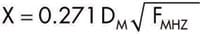
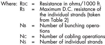
Where:
DM =Wire diameter in mils
FMHZ = Frequency in megahertz
From Table 1 and other empirical data the following table of recommended wire gauges vs. frequency for most Litz wire constructions has been prepared.
| Frequency | Recommended Wire Gauge | Nominal Diameter Over Copper | DC Resistance OHMS/M FT (Max) | Single Strand RAC/RDC “H” |
|---|---|---|---|---|
| 60 Hz to 1kHz | 28 AWG | 0.0126 | 66.37 | 1.0000 |
| 1 kHz to 10 kHz | 30 AWG | 0.0100 | 105.82 | 1.0000 |
| 10 kHz to 20 kHz | 33 AWG | 0.0071 | 211.70 | 1.0000 |
| 20 kHz to 50 kHz | 36 AWG | 0.0050 | 431.90 | 1.0000 |
| 50 kHz to 100 kHz | 38 AWG | 0.0040 | 681.90 | 1.0000 |
| 100 kHz to 200 kHz | 40 AWG | 0.0031 | 1152.30 | 1.0000 |
| 200 kHz to 350 kHz | 42 AWG | 0.0025 | 1801.00 | 1.0000 |
| 350 kHz to 850 kHz | 44 AWG | 0.0020 | 2873.00 | 1.0003 |
| 850 kHz to 1.4 MHz | 46 AWG | 0.0016 | 4544.00 | 1.0003 |
| 1.4 MHz to 2.8 MHz | 48 AWG | 0.0012 | 7285.00 | 1.0003 |
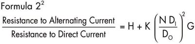
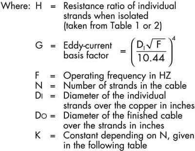
After the individual wire gauge has been determined and assuming that the Litz wire construction has been designed such that each strand tends to occupy all possible positions in the cable to approximately the same extent, the ratio of A.C. to D.C. resistance of an isolated Litz wire conductor can be determined from the following formula.
| N | 3 | 9 | 27 | Infinity |
|---|---|---|---|---|
| K | 1.55 | 1.84 | 1.92 | 2 |
The D.C. resistance of a Litz wire conductor is related to the following parameters:
- AWG of the individual strands.
- Number of strands in the cable.
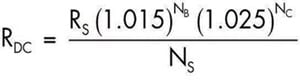
- Factors relating to the increased length of the individual strands per unit length of cable (take-up). For normal Litz wire constructions a 1.5% increase in D.C. resistance for every bunching operation and a 2.5% increase in D.C. resistance for every cabling operation are approximately correct.
The following formula derived from these parameters for the D.C. resistance of any Litz construction is:
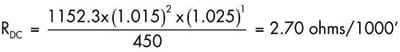
Following is an example of the calculations required to evaluate a Type 2 Litz wire construction consisting of 450 strands of 40 AWG single-film polyurethane-coated wire operating at 100 KHZ. This construction, designed with two bunching operations and one cabling operation, would be written 5×3/30/40 (NEW uses “x” to indicate a cabling operation and “/” to indicate a bunching operation).
1. Calculate the D.C. resistance of the Litz wire construction using formula 3.
2. Calculate the A.C. to D.C. resistance ratio using formula 2.
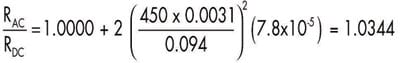
3. The A.C. resistance is, therefore, 1.0344 x 2.70 or 2.79 ohms/1 000 ft.
The value of Litz wire can easily be seen if the above example is compared with a solid round wire with equivalent cross-sectional area, 65.8 mils in diameter. Using the same operating parameters, the D.C. resistance is 2.395 ohms/ 1000 ft. However, the A.C./D.C. resistance ratio increases to approximately 21 .4 making the A.C. resistance 51 .3 ohms/1000 ft.


